TCR-SLE GEN2 Quickstart
Thank you for choosing a Parametric Analytics product. You have chosen a quality product Made in Switzerland. Each counter is handmade and individually tested.
This Quick Start Guide explains all the steps necessary to get the device up and running. Click on the images to enlarge them.
Further information like LoRaWAN® integration, payload decoding can be found in the TCR Users Manual.
1. UNBOXING
Check content
Open the box and check the contents.
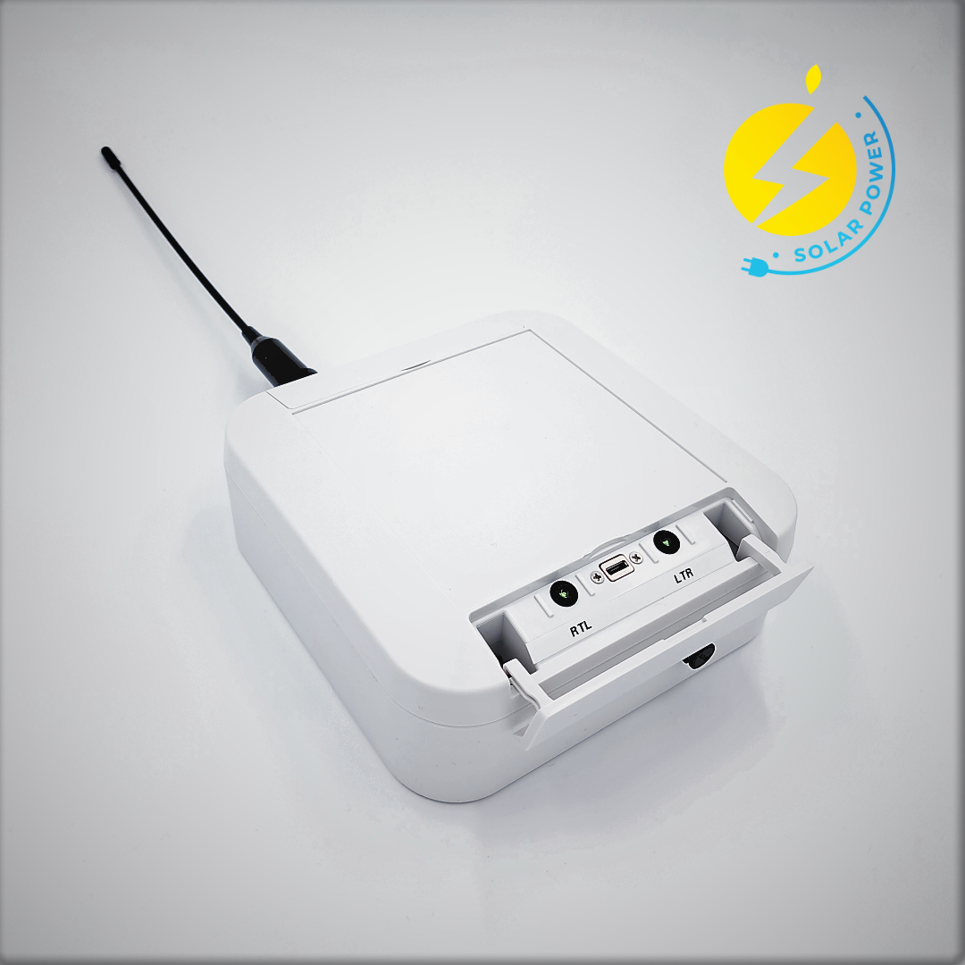 |
TCR-SLE Live Radar Traffic Counter GEN2, Solar powered |
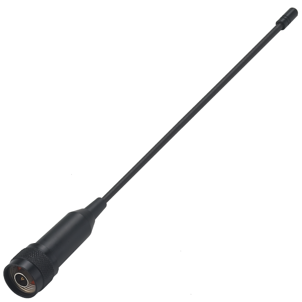 |
2244 External 868MHz Outdoor Antenna, N Type(M) Connector, l=243 mm |
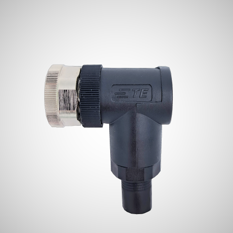 |
M12SOL Adapter plug for connecting Parametric's SOL17 or SOL9 panels to the M12 socket on the side of the counter. |
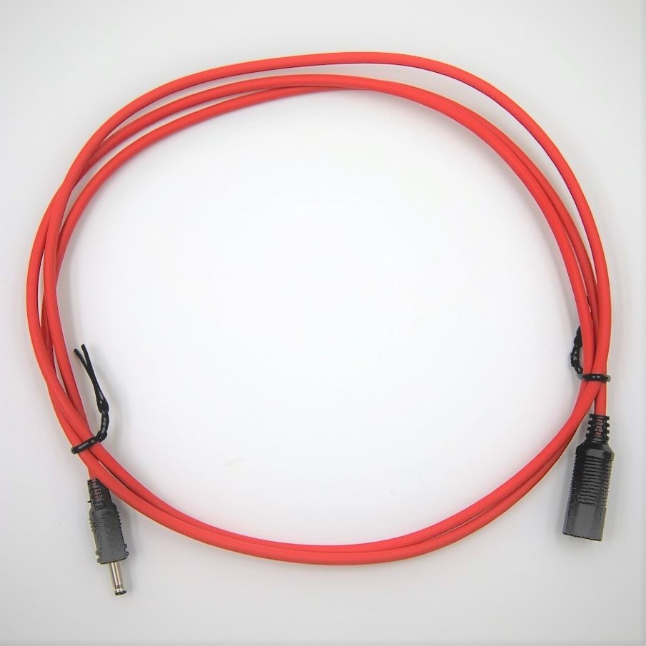 |
SOL-EXT4 Extension cable for solar panels, 120cm (4 feet) |
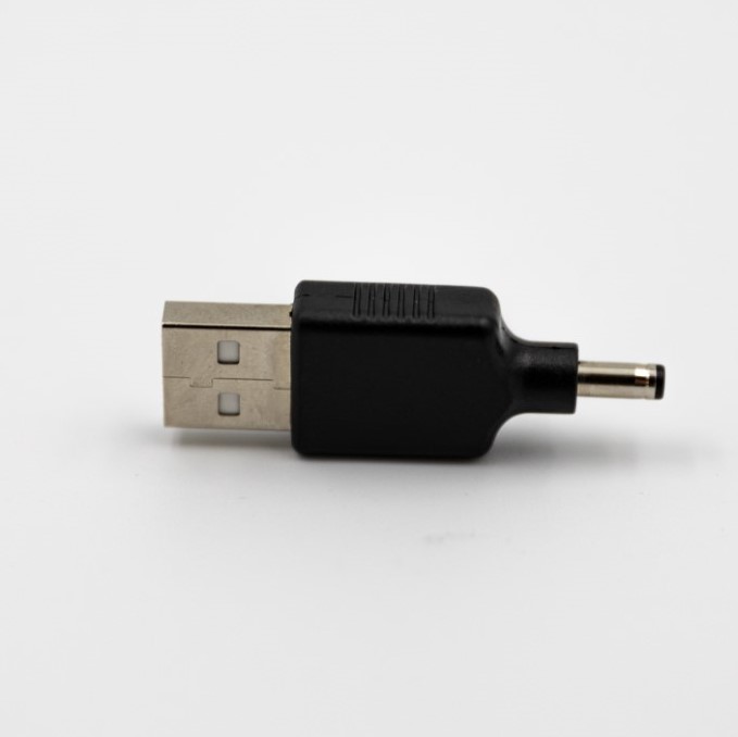 |
1943 USB Charging Adapter for pre-charge the counters without connecting the solar panel. |
Optional parts when ordered together with the counter.
 |
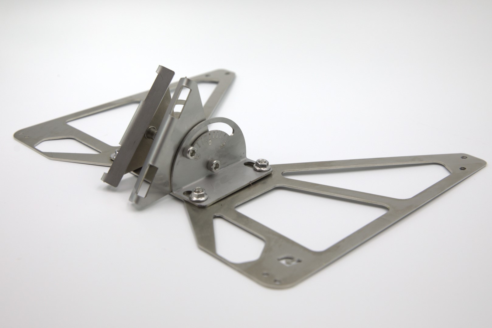
MT80-15 Bracket to mount the device to a pole or flat surface. The holder can be tilted. Mounting screws for the counter are included. Material to attach the holder to a mast is not included. |
  |
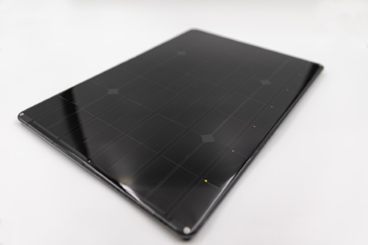
SOL9-KIT The kit shared_content a rugged 9W solar panel (SOL9) and Parametric's adjustable solar pole (SOLMT) as well as mounting nuts. Material to attach the mount to a mast is not included |
 |
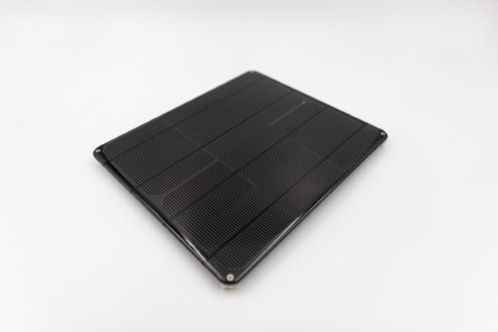
SOL17-KIT The kit shared_content a rugged 17W solar panel (SOL17) and Parametric's adjustable solar pole (SOLMT) as well as mounting nuts. Material to attach the mount to the mast is not included |
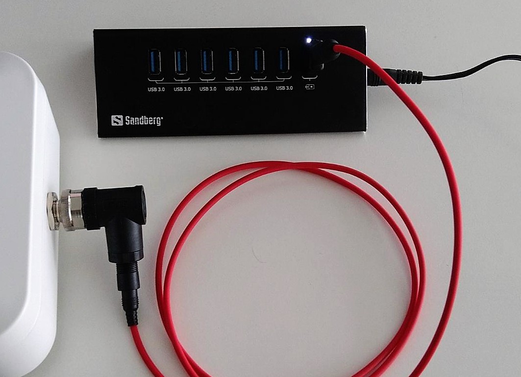
Charge battery first
As long as the device is not yet installed outdoors, it should be charged with the included USB adapter. This keeps the battery fresh and prevents damage from deep discharge.
Push the plug from SOL_EXT4 cable into the socket of the M12SOL adapter. Then connect the plug of the USB Adapter with the other end.
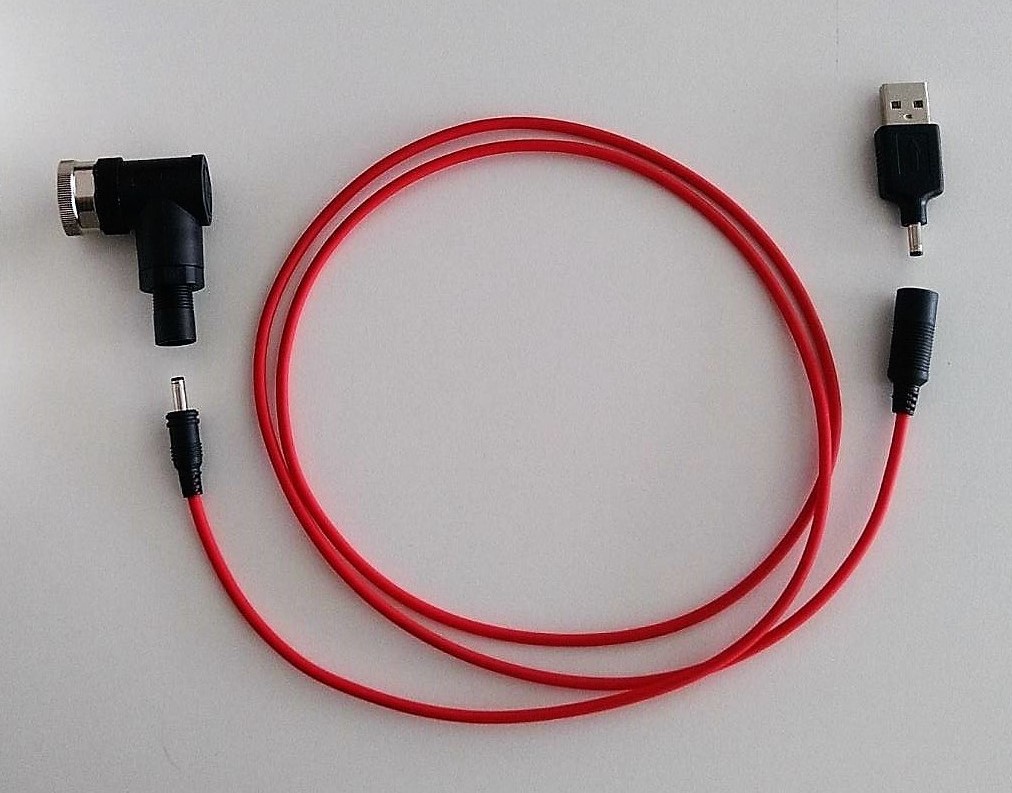
Connect USB Adapter with an USB port of your PC or (better) a USB hub.
2. PLANNING
To achieve the most accurate measurement possible, planning the installation is essential.
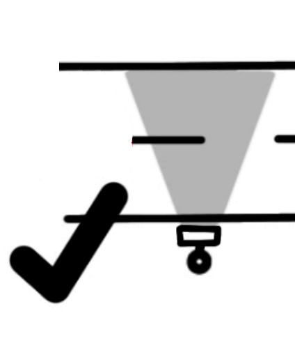
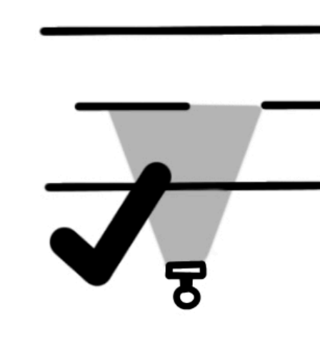
Horizontal or Top Down?
The devices can be operated both directly next to the road or elevated and looking down from above. We recommend using a laser measuring tool or a laser pointer to align the device correctly.
 |
When mounted on a pole or mast you should point the sensor to the middle of the road (center line). This can be done easily by adjusting the tiltable bracket MT80-15. The bracket can be placed about 3-4 meters above ground. Please check the max range of the sensor. Important: The pole must not move in the wind |
 |
When mounted next to the street we recommend a mounting height of 1.2-1.5m above ground. Line of sight should be completely horizontal. |
Important Rules
The device works best when the following rules are observed.
 |
Lateral to movement TCR are side radars that detect motion from both directions simultaneously. The movement should be linear. Therefore place the sensor parallel to the movements direction and keep away from curves, crossings, driveways |
 |
Distance to object LS-Devices: The sensor must be placed at least 50cm away from the target. HS-Devices: The sensor must be placed at least 3m away from the target. |
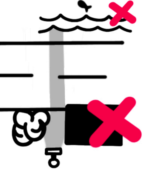 |
Avoid obstacles in FOV Make sure there are no obstacles such as walls, street signs, shrubberies, trees in the field of view. When placed beside water the device might detect the waves. |
LTR vs RTL
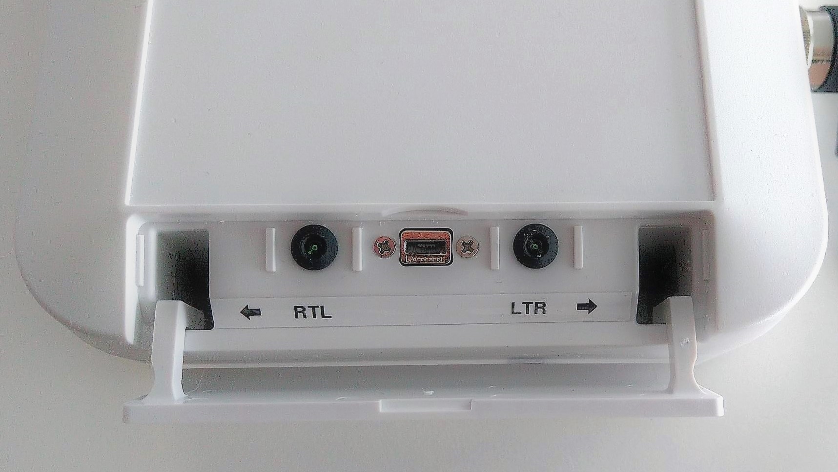
The TCR traffic counters distinguish between 2 directions.
RTL
objects which come from the right and disappear to the left. The left LED will pulse once in this case.
LTR
objects which come from the left and disappear to the right. The right LED will pulse once in this case.
Measure distance to lanes
In order for the device to determine the velocities, the distance to the object must be known. The distance can be determined with a tape measure or a laser distance meter. Measurements are taken from the middle of a track to the front of the device.
- RTLDist = Distance in cm to the RTL movement line.
- LTRDist = Distance in cm to the LTR movement line.
| Situation | |
|---|---|
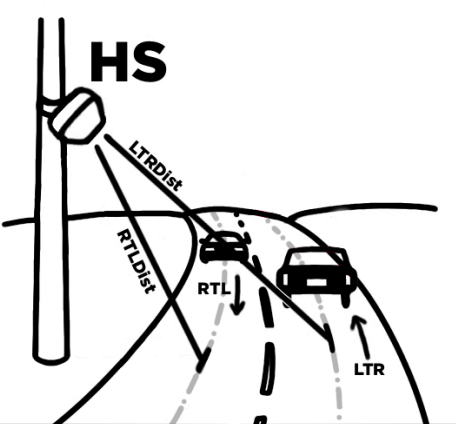 |
Two lanes, cross traffic (2L2D) This is typical for HS applications such as measuring traffic on interstate roads. RTLDist and LTRDist are different. |
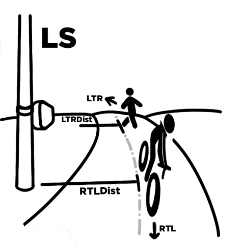 |
Cross traffic on one lane (1L2D) This is typical for low speed traffic (LS) measuring bicycle lanes or small paths. In this case get the distance to the center of the track and set RTLDist and LTR Dist to the same value. |
3. CONFIGURATION
Connect USB cable
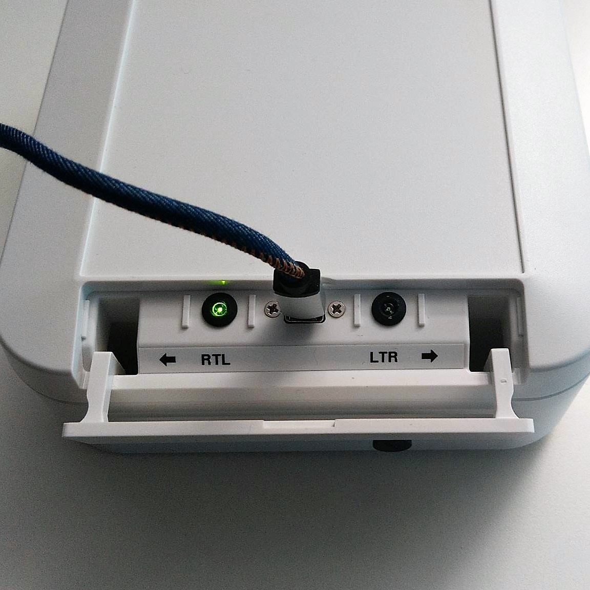
Open the service lid and connect a USB-to-Micro-USB cable Connect the other end to a Windows PCs USB-Port. The RTL LED should start to blink.
Configure using PPX
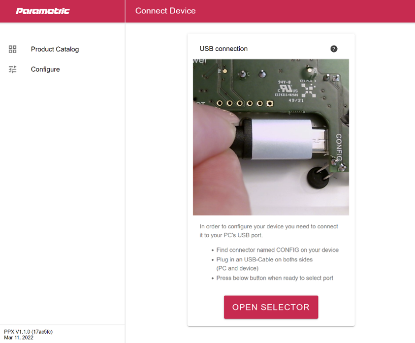
While the device is connected to the PC open ppx.parametric.ch to access the online configuration tool. Follow the instructions on the screen to establish a connection.
Set Distance to Lanes
Once connected open Radar-Settings and find Left To Right Lane Distance and Right To Left Lane Distance
- Enter LTRDist value you measured in #measure-distance-to-lanes) into the field LTRDist
- Enter RTLDist value you measure in #measure-distance-to-lanes) into the field RTLDist
- Press Save
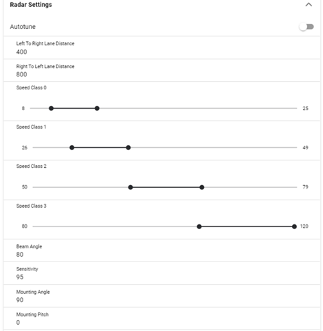
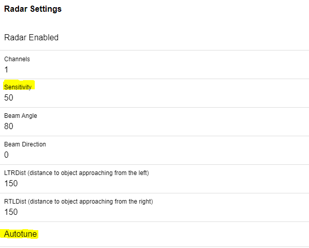
Sensitivity
Turn on autotune to allow the radar to adjust the sensitivity.
After entering LTRDist and RTLDist the sensitivity is automatically determined based on those values. The further the distance to the measurement, the higher the sensitivity.
Note: Small adjustments of sensitivity can be done manually. If the ratio (sensitivity vs. RTL/LTR) is not correct, the radar may incorrectly categorize the measured object.
4. INSTALLATION
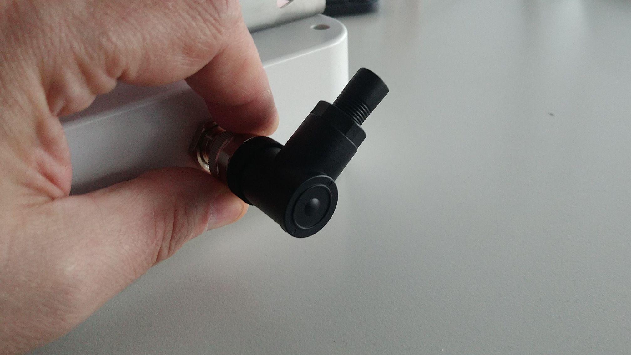
M12 Solar Adapter Plug
The M12 connectors have a coding notch (A Coding).
Important:
Check the pins before plugging in
Rotate the plug so that the notch matches the pin in the socket
Carefully insert the plug by hand
Gently tighten knurled screw by hand
Plug the MP12SOL adapter onto the M12 socket and tighten the ring by hand.
Mount MT80
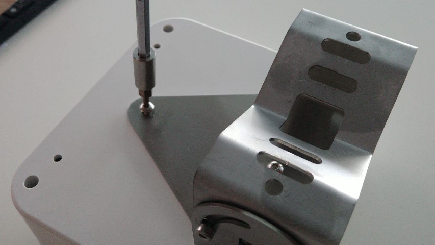
Carefully tighten the MT80-15 holder with the supplied screws. Use a 25 HEX screw driver for that.
Warning: Using longer screws could crack the enclosure.
Extend the Solar Cable
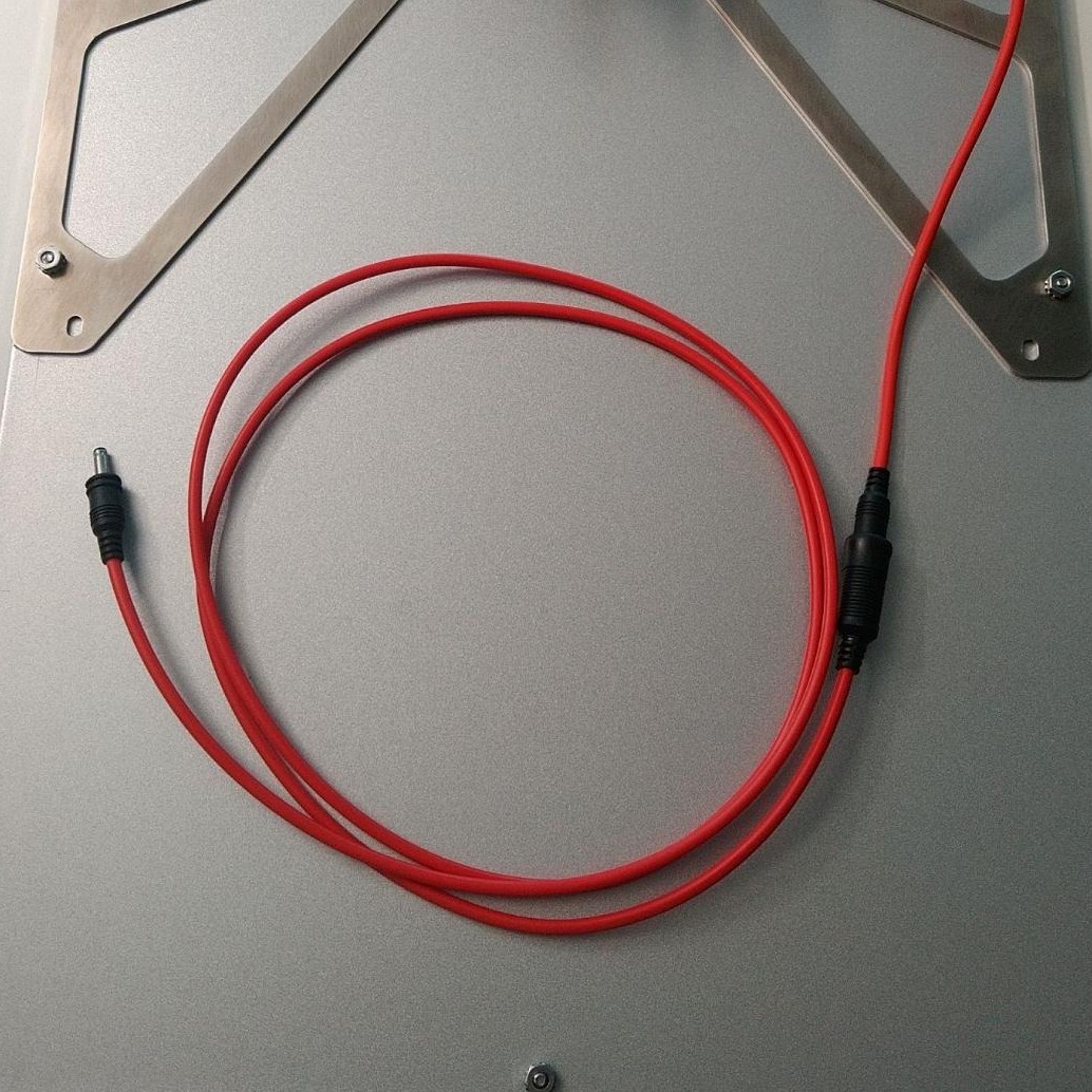
Use the SOL-EXT4 extension cable if you mount the solar panel more then 20cm away from the counter.
Installing the Counter
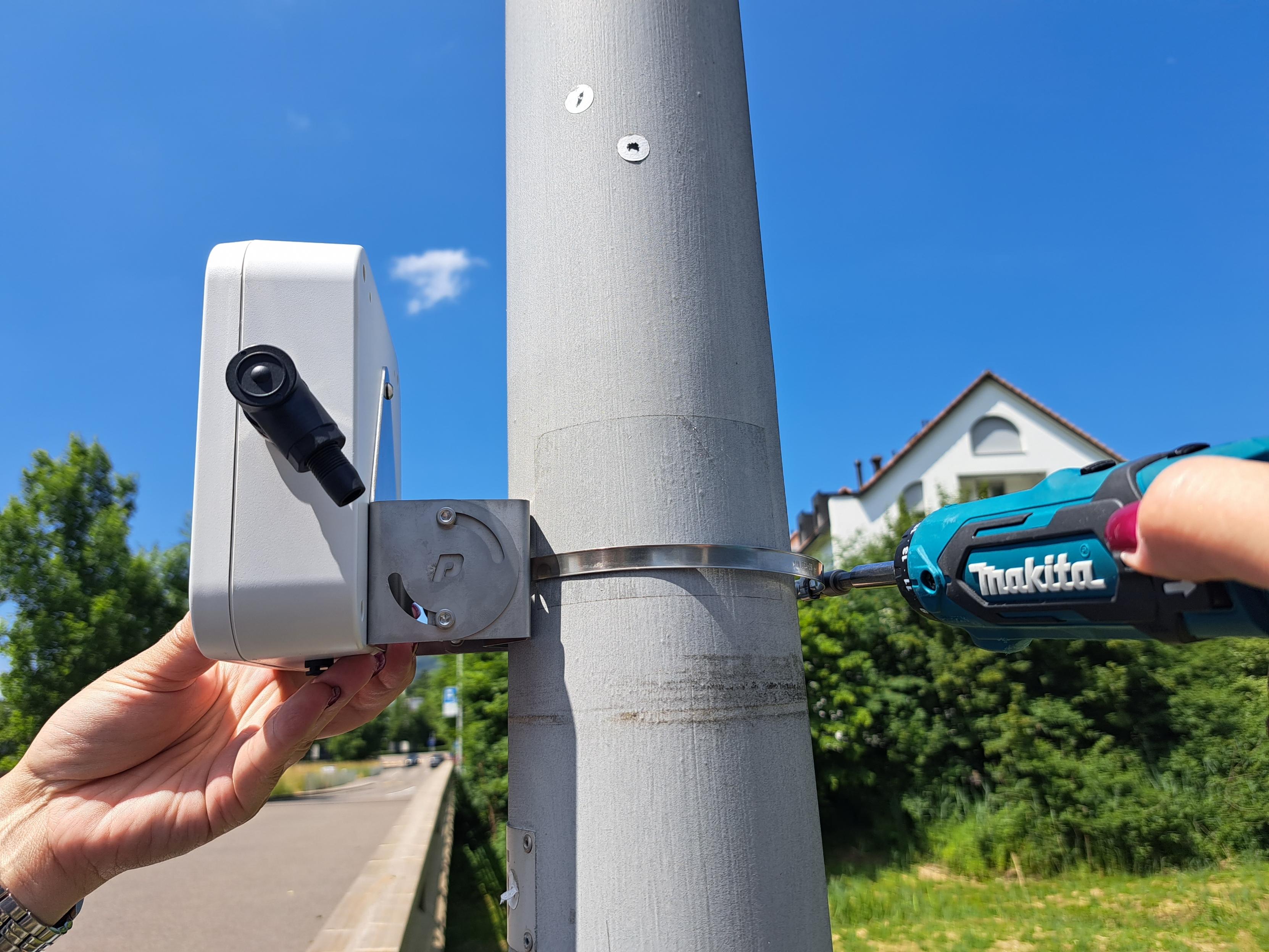
If you mount the counter to a pole or mast use pipe clamps or metal straps of suitable length to secure MT80-15 bracket.
Installing the Solarpanel
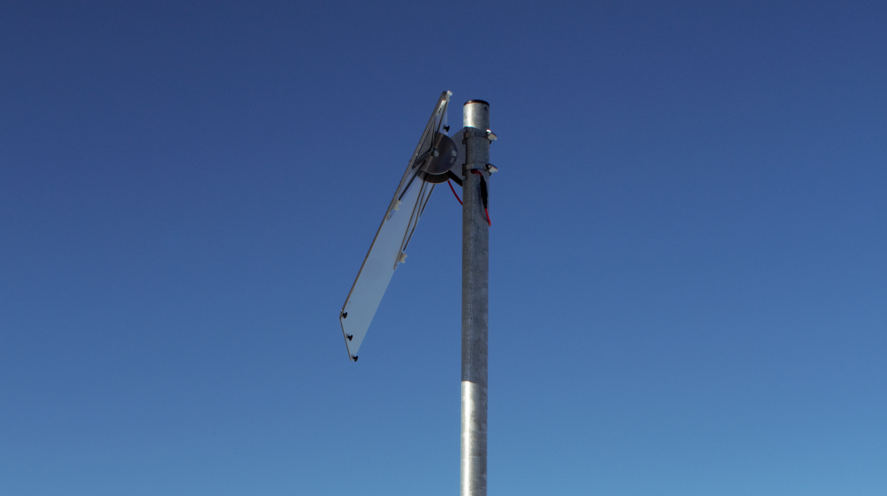
Mount the solar panel in a place where it gets enough sunlight during the day. Use pipe clamps or metal straps of suitable length to secure the bracket to the pole.
Adjust to pole diameter
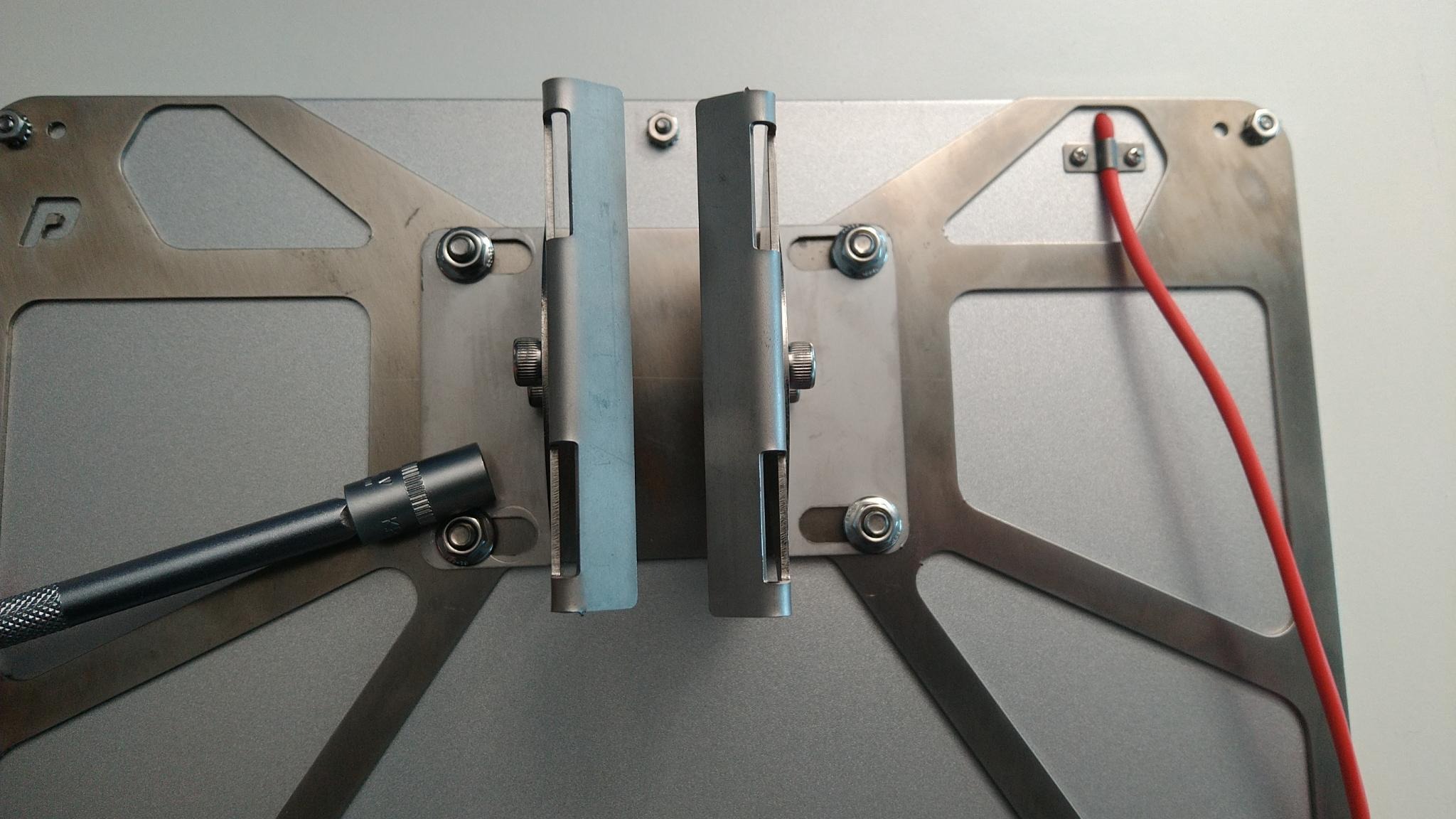
Adjust SOLMT bracket to match your pole diameter.
Adjust azimuth
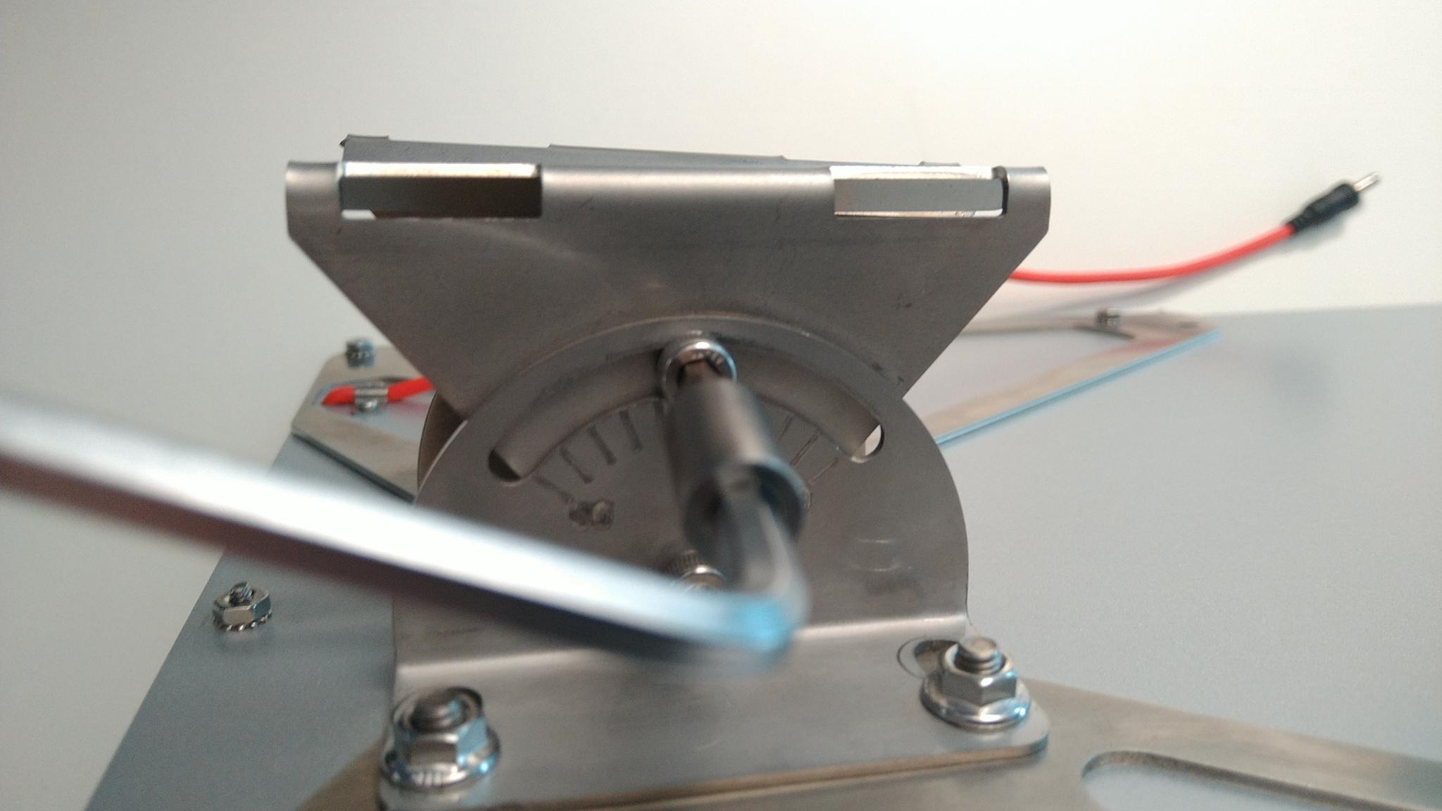
You can change the angle of the solar panel to harvest more solar energy. Or you can fix the panel in a vertical position so that no snow or dust can remain on it.
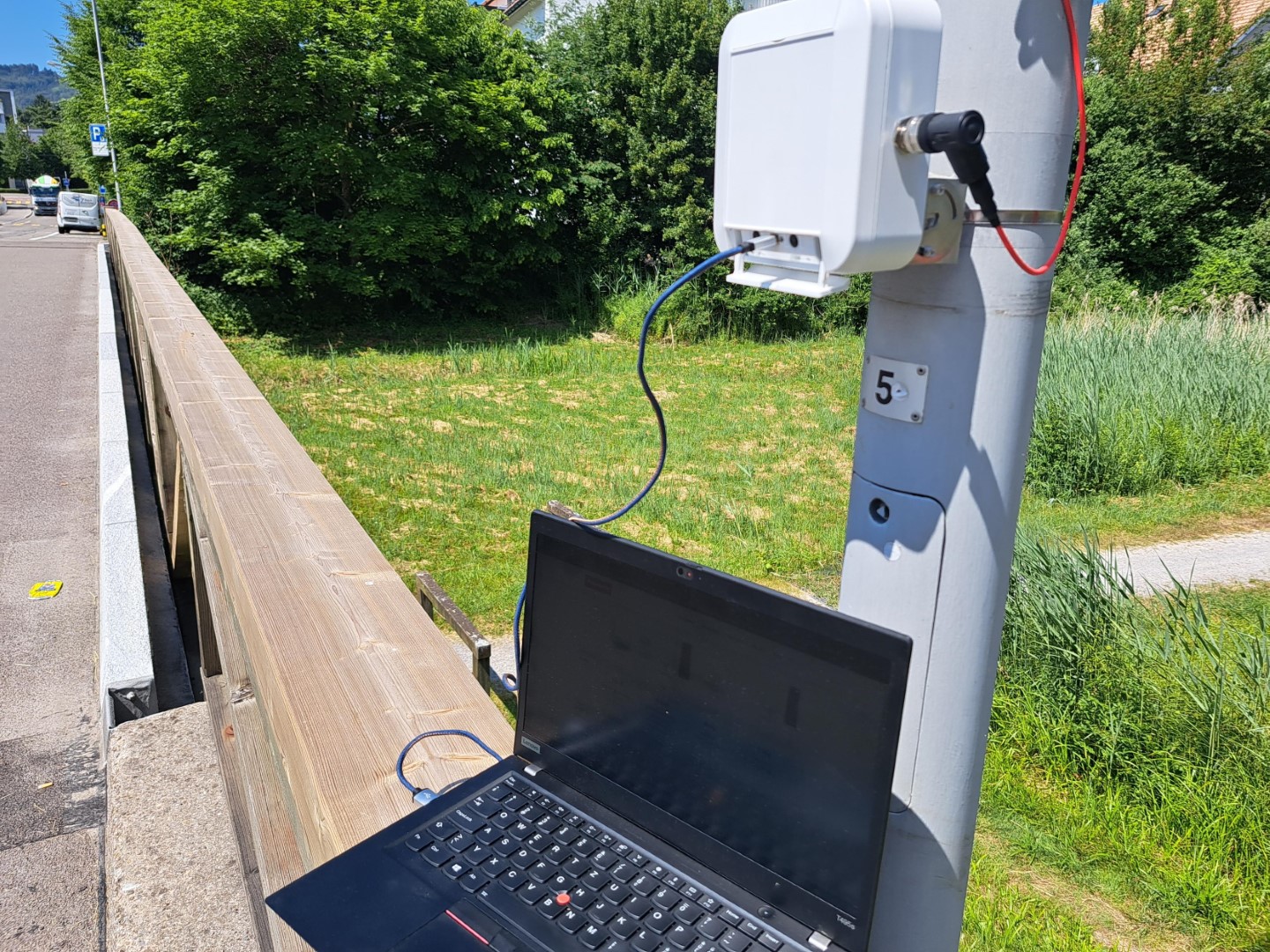
5. TESTING
Live Data Monitoring
Go outside to your TCR, connect the USB cable and start live measurements on site. While the device is connected to the PC open ppx.parametric.ch to access the online configuration tool.
Last Detection
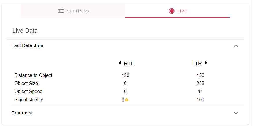
Last Detection gives you an insight to the last radar measurement. This is what the radar “sees”.
| Category | Description |
|---|---|
| Distance to Object | LTRDist and RTLDist setting |
| Object Size | the length of all radar reflexions seen |
| Object Speed | the lateral velocity |
| Signal quality | should be 100% when the object is in field of view and not too near |
Counters
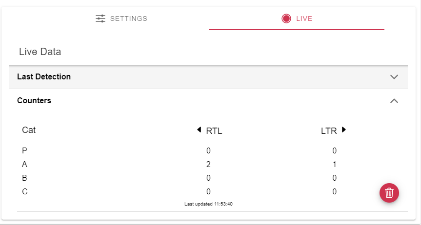
Counters is a table with all Categories an left / right counter values. Values are updated regularely
Adjust your values
The main challenge with the TCR devices is to find a suitable Distance/Sensitivity Setting.
If the sensitivity is to high, the object might blur and therefore gets too big (Size value) If the distance is incorrect the size get too big too.
With Autotune enabled the Radar Sensitivity will be controlled automatically. It’s comparable to the automatic exposure setting at a photo camera.
Disclaimer
ALL PRODUCT, PRODUCT SPECIFICATIONS AND DATA ARE SUBJECT TO CHANGE WITHOUT NOTICE TO IMPROVE RELIABILITY, FUNCTION OR DESIGN OR OTHERWISE.
PMY Systems AG, its affiliates, agents, and employees, and all persons acting on its or their behalf (collectively, "PMX"), disclaim any and all liability for any errors, inaccuracies or incompleteness contained in any datasheet or in any other disclosure relating to any product.
PMX makes no warranty, representation or guarantee regarding the suitability of the products for any particular purpose or the continuing production of any product. To the maximum extent permitted by applicable law, PMX disclaims (i) any and all liability arising out of the application or use of any product, (ii) any and all liability, including without limitation special, consequential or incidental damages, and (iii) any and all implied warranties, including warranties of fitness for particular purpose, non-infringement and merchantability.
Statements regarding the suitability of products for certain types of applications are based on PMX's knowledge of typical requirements that are often placed on Paramtric products in generic applications. Such statements are not binding statements about the suitability of products for a particular application. It is the customer's responsibility to validate that a particular product with the properties described in the product specification is suitable for use in a particular application. Parameters provided in datasheets and / or specifications may vary in different applications and performance may vary over time. All operating parameters, including typical parameters, must be validated for each customer application by the customer's technical experts. Product specifications do not expand or otherwise modify Paramtric's terms and conditions of purchase, including but not limited to the warranty expressed therein.
Hyperlinks may direct users to third-party websites. These links are provided as a convenience and for informational purposes only. Inclusion of these hyperlinks does not constitute an endorsement or an approval by PMX of any of the products, services or opinions of the corporation, organization or individual associated with the third-party website. PMX disclaims any and all liability and bears no responsibility for the accuracy, legality or content of the third-party website or for that of subsequent links.
Except as expressly indicated in writing, PMX products are not designed for use in medical, life-saving, or life-sustaining applications or for any other application in which the failure of the PMX product could result in personal injury or death. Customers using or selling PMX products not expressly indicated for use in such applications do so at their own risk. Please contact authorized PMX personnel to obtain written terms and conditions regarding products designed for such applications.
No license, express or implied, by estoppel or otherwise, to any intellectual property rights is granted by this document or by any conduct of PMX. Product names and markings noted herein may be trademarks of their respective owners