TCR LoRaWAN® Payload Description
This document describes LoRaWAN® Payload formats of Parametric TCR Traffic Counters used in Firmware V2.2
Changes made in this version of the document.
- New Counter Payload V2. (Changed sbx_batt to voltage to get either DC power or SBX voltage)
- Fixed downlink command
c152radar_channel
Payload Types
TCR devices send 3 different payloads types. Each payload has a unique prefix to easily separate them. In addition, different ports are used in each case.
| Format | Prefix | Bytes | Port | Uplink | Downlink |
|---|---|---|---|---|---|
| DeviceID Payload V2 | be02xxd2 | 10 | 190 | once | n/a |
 Counters Payload V2 Counters Payload V2 |
a2 |
10 | 14, 15, 16, 17 | interval | on request |
| Config Payload V1 | c1 | 6-7 | 1 | on request | on request |
DeviceID Payload (Port 190)
After TCR has successfully joined a LoRaWAN® network, a DeviceID payload is sent once via port 190.
The DeviceID payload contains device identification data and firmware version information. This can be useful in large installations to maintain a device inventory with information such as type and firmware version. If this is not needed, ignore this payload data.
Downlinks to port 190 will be ignored.
Payload Format
| Byte | Property | Description | Uplink Values | Downlink Values |
|---|---|---|---|---|
| 0 | vid | Vendor ID be for Parametric Devices |
be | n/a |
| 1 | dev_fam | Device Family 02 : TCR |
02 | n/a |
| 2 | dev_type | Device Type 00 : TCR-LS 01 : TCR-LSS 02 : TCR-HS 03 : TCR-HSS 04 : TCR-LSA 05 : TCR-LSB 06 : TCR-HSA 07 :TCR-HSB 08 : TCR-LSBS 09 : TCR-HSBS 0a : TCR-DLI 0b : TCR-DLE 0c : TCR-SLI 0d : TCR-SLE |
00-0d | n/a |
| 3 | pay_type | d2 = DeviceID Payload V2 | d2 | n/a |
| 4 | speedclass | Device Speed Class Config 00 : P 01 : LS 02 : HS TCR GEN2 devices only |
00-02 | n/a |
| 5 | Future use | n/a | n/a | |
| 6 | fw_maj_min | Firmware Major/Minor Version Number | 20 | n/a |
| 7 | fw_fix | Firmware Bugfix Version Number | 00-ff | n/a |
| 8 | sbx_maj_min | SBX Firmware Major/Minor Version Number | 20 | n/a |
| 9 | sbx_fix | SBX Firmware Bugfix Version Number | 00-ff | n/a |
Total length: 10 bytes (20 ASCII characters)
Examples
| DeviceID Payload | |
|---|---|
be020ad2010020000000 |
TCR-DLI with firmware 2.1.0, Speed Class Config 'LS', no solar unit |
be020dd2020020014200 |
TCR-SLE with firmware 2.1.0, Speed Class Config 'HS', solar unit V4.2.0 |
Counter Payload (Port 14, 15, 16, 17)
Counter data is sent at regular intervals or on detection (totalizer mode).
To save airtime, the payload has been reduced to 10 bytes. This allows operation in all major LoRaWAN® regions such as EU868, AS923, AU915 and US915.
Payload Format
| Byte | Property | Description | Uplink Values | Downlink Values |
|---|---|---|---|---|
| 0 | pay_type | a2 = Counter Payload V2 | a2 | a2 |
| 1-2 | data{x}_timestamp | Timestamp of data, Hours (GMT) HHMM | 0000-2359 | - |
| 3-4 | l{x}_cnt | Left-to-right counter value x = 0, 1, 2, 3 (Cat. P, A, B, C) |
0000-ffff | 0000-ffff |
| 5 | l{x}_avg | Left-to-right average speed [km/h] x = 0, 1, 2, 3 (Cat. P, A, B, C) |
0000-ffff | - |
| 6-7 | r{x}_cnt | Right-to-left counter value x = 0, 1, 2, 3 (Cat. P, A, B, C) |
0000-ffff | 0000-ffff |
| 8 | r{x}_avg | Right-to-left average speed [km/h] x = 0, 1, 2, 3 (Cat. P, A, B, C) |
0000-ffff | - |
| 9 | voltage |
Power supply voltage (dc power or solar power) Multiply with 100 to get mV dc power measurement is currently limited to 6600mV due to a hardware limitation |
0000-ffff | - |
{x} : 0, 1, 2, 3
Total length: 10 bytes (20 ASCII characters)
Ports used
Counter data are sent on different ports to indicate different traffic classes. As an example car category will always be sent using port 16.
Note: Not all payloads are used on all device types.
| Uplink Port | Used for | TCR-xxx/LS | TCR-xxx/HS |
|---|---|---|---|
| 14 | Cat P (People) Counter | X | |
| 15 | Cat A (Two-wheelers) Counter | X | X |
| 16 | Cat B (Cars) Counter | X | |
| 17 | Cat C (HGV) Counter | X |
Examples
| Counter Uplinks | |
|---|---|
a113140001010002044e received at port 14 |
Traffic Category P. 1 counted from left with average speed of 1km/h. 2 counted from right with speed 4 km/h. Data Time: 19:20 GMT. Battery: 7800mV |
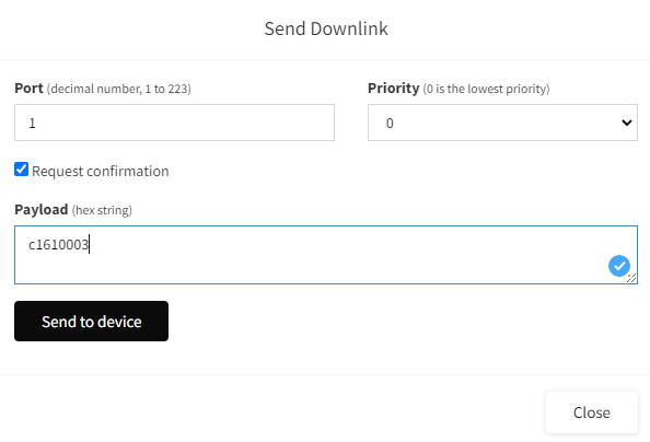
Config Downlinks (Port 1)
Config downlinks are used to change device settings remotely. A key / value pair is sent to the device for this purpose.
Config Payloads are sent and received at port 1. As soon as the device receives a downlink, the setting will be range-checked and saved to ROM. The devices applies most of the settings during operation.
Note: It is a good idea to send a
c1eewhen you are done to let the device restart and re-join.
Payload Format
| Byte | Property | Description | Uplink Values | Downlink Values |
|---|---|---|---|---|
| 0 | pay_type | c1 = Config Payload V1 | c1 | c1 |
| 1 | key | Setting | 01-ee | 01-ee |
| 2-3 | value | Value to change | 0000-ffff | 0000-ffff |
Total length: 4 bytes (8 ASCII characters)
Application Settings
Downlinks to change application settings. Send c1ee to apply settings an restart the device.
| Write Command | Read Command | Setting | Description | Examples |
|---|---|---|---|---|
c141xxxx |
c141 |
mode | Change operation mode 0x0000 : Interval 0x0001 : NotZero 0x0002 : Trigger |
Switch to interval modec1410000 |
c142xxxx |
c142 |
holdoff | Set holdoff time 0x0000-0x0258 : 0-600s |
Disable holdoffc1420000 |
c143xxxx |
c143 |
timeout | Set auto-zero timeout in minutes 0x0000 : disabled 0x0001-0x05a0 : 1-1440min |
Disable auto-zeroc1430000 |
c144xxxx |
c144 |
sumup | Enable totalizer instead of interval counting 0x0000 : interval counter 0x0001 : totalizer |
Enable interval counting c1440000 |
c145xxxx |
c145 |
fallbackcat | Set fallback category 0x0000 : Cat P (People) 0x0001 : Cat A (Two-Wheelers) 0x0001 : Cat B (Cars) 0x0002 : Cat C (HGV) |
Set fallback category cars (B)c1450002 |
Traffic Categories
Downlinks to configure traffic categorization. This includes object size and speed of an object. If both values are in the defined range, the object will be marked to be cat 0, 1, 2 or 3.
Following tables shows default categories enabled by device type. However it is possible to enable all categories on all types.
| Cat | Used for | TCR-DLx/LS | TCR-SLx/LS | TCR-DLx/HS | TCR-SLx/HS |
|---|---|---|---|---|---|
| P | People | X | X | ||
| A | Two Wheelers | X | X | X | X |
| B | Cars | X | X | ||
| C | Trucks | X | X |
Cat P
Following downlinks are used to configure people detection filters. Send c1ee to apply settings an restart the device.
| Write Command | Read Command | Setting | Description | Example |
|---|---|---|---|---|
c101xxxx |
c101 |
cat_p_enabled | Enable Category P 0x0000 : disabled 0x0001 : enabled |
Enable people countingc1010001 |
c104xxxx |
c104 |
cat_p_min_size | Change min object size of category P 0x0000-0x03E8 : 0-1000cm |
Set min object size to 1cmc1040001 |
c105xxxx |
c105 |
cat_p_max_size | Change max object size of category P 0x0000-0x03E8 : 0-1000cm |
Set max object size to 100cmc1050064 |
c106xxxx |
c106 |
cat_p_min_speed | Change min object speed of category P 0x0001-0x0078 : 1-120km/h |
Set min object speed to 1km/hc1060001 |
c107xxxx |
c107 |
cat_p_max_speed | Change max object speed of category P 0x0001-0x0078 : 1-120km/h |
Set min object speed to 7km/hc1070007 |
Cat A
Following downlinks are used to configure detection of bicycles or motorbikes. Send c1ee to apply settings an restart the device.
| Write Command | Read Command | Setting | Description | Example |
|---|---|---|---|---|
c111xxxx |
c111 |
cat_a_enabled | Enable Category A 0x0000 : disabled 0x0001 : enabled |
Enable bike countingc1110001 |
c114xxxx |
c114 |
cat_a_min_size | Change min object size of category A 0x0000-0x03E8 : 0-1000cm |
Set min object size to 100cmc1140064 |
c115xxxx |
c115 |
cat_a_max_size | Change max object size of category A 0x0000-0x03E8 : 0-1000cm |
Set max object size to 200cmc11500c8 |
c116xxxx |
c116 |
cat_a_min_speed | Change min object speed of category A 0x0001-0x0078 : 1-120km/h |
Set min object speed to 5km/hc1160005 |
c117xxxx |
c117 |
cat_a_max_speed | Change max object speed of category A 0x0001-0x0078 : 1-120km/h |
Set min object speed to 40km/hc1170028 |
Cat B
Following downlinks are used to configure detection of cars. Send c1ee to apply settings an restart the device.
| Write Command | Read Command | Setting | Description | Example |
|---|---|---|---|---|
c121xxxx |
c121 |
cat_b_enabled | Enable Category B 0x0000 : disabled 0x0001 : enabled |
Enable bike countingc1210001 |
c124xxxx |
c124 |
cat_b_min_size | Change min object size of category B 0x0000-0x03E8 : 0-1000cm |
Set min object size to 250cmc12400fa |
c125xxxx |
c125 |
cat_b_max_size | Change max object size of category B 0x0000-0x03E8 : 0-1000cm |
Set max object size to 600cmc1250258 |
c126xxxx |
c126 |
cat_b_min_speed | Change min object speed of category B 0x0001-0x0078 : 1-120km/h |
Set min object speed to 10km/hc126000a |
c127xxxx |
c127 |
cat_b_max_speed | Change max object speed of category B 0x0001-0x0078 : 1-120km/h |
Set min object speed to 100km/hc1270064 |
Cat C
Following downlinks are used to configure detection of heavy vehicles (HGV). Send c1ee to apply settings an restart the device.
| Write Command | Read Command | Setting | Description | Example |
|---|---|---|---|---|
c131xxxx |
c131 |
cat_c_enabled | Enable Category C 0x0000 : disabled 0x0001 : enabled |
Enable bike countingc1310001 |
c134xxxx |
c134 |
cat_c_min_size | Change min object size of category C 0x0000-0x03E8 : 0-1000cm |
Set min object size to 600cmc1340258 |
c135xxxx |
c135 |
cat_c_max_size | Change max object size of category C 0x0000-0x03E8 : 0-1000cm |
Set max object size to 1000cmc13503e8 |
c136xxxx |
c136 |
cat_c_min_speed | Change min object speed of category C 0x0001-0x0078 : 1-120km/h |
Set min object speed to 10km/hc136000a |
c137xxxx |
c137 |
cat_c_max_speed | Change max object speed of category C 0x0001-0x0078 : 1-120km/h |
Set min object speed to 80km/hc1370050 |
Radar Settings
Downlinks to change radar settings. Send c1ee to apply settings an restart the device.
| Write Command | Read Command | Setting | Description | Example |
|---|---|---|---|---|
c151xxxx |
c151 |
radar_enabled | Switch radar module on/off 0000 : off 0001 : on |
Switch offc1510000 |
c152xxxx |
c152 |
radar_channel | Choose Radar Channel 0001 or 0002< | Set to Channel 2c1520002 |
c153xxxx |
c153 |
radar_sens | Change Radar Sensitivity Level [%] | Set sensitivity to 95%c153005f |
c154xxxx |
c154 |
radar_beam | Change Virtual Radar Beam Angle 30-80° | Set Angle 70°c1540046 |
c155xxxx |
c155 |
radar_dir | Change Virtual Radar Beam Direction (+30 = right, -30 = to the left) | Set direction straight (0°)c1550000 |
c156xxxx |
c156 |
radar_ltrdist | Min Distance to object from left (LTRDist) 50-1000cm |
Set 4.5m c15601c2 |
c157xxxx |
c157 |
radar_rtldist | Min Distance to object from right (RTLDist) 50-1000cm |
Set 2.5m c15700fa |
c158xxxx |
c158 |
radar_autotune | Enable Autotune for the next 10 detections 0000 : off 0001 : on |
Enable Autotunec1580001 |
LoRaWAN® Settings
Downlinks to change some LoRaWAN® settings. Send c1ee to apply settings an restart the device.
| Write Command | Read Command | Setting | Description | Example |
|---|---|---|---|---|
c161xxxx |
c161 |
lora_interval | Change LoRa Uplink interval in [min] 0001...05a0 |
Set interval to 10minc161000a |
c162xxxx |
c162 |
lora_class | Set LoRaWAN® Device class A: 0000 C: 0002 |
Switch to class Cc1620002 |
c163xxxx |
c163 |
lora_confirmed | Set uplink mode unconfirmed: 0000 confirmed: 0001 |
Disable confirmed uplinksc1630000 |
Device Control Commands
These downlinks are used to execute commands on the device
| Command | Description | Example |
|---|---|---|
c102xxxx |
Overwrite L0 counter 0x0000-0xffff : 0-65535 |
Zero L0 counterc1020000 |
c103xxxx |
Overwrite R0 counter 0x0000-0xffff : 0-65535 |
Zero R0 counterc1030000 |
c112xxxx |
Overwrite L1 counter 0x0000-0xffff : 0-65535 |
Zero L1 counterc1120000 |
c113xxxx |
Overwrite R1 counter 0x0000-0xffff : 0-65535 |
Zero R1 counterc1130000 |
c122xxxx |
Overwrite L2 counter 0x0000-0xffff : 0-65535 |
Zero L2 counterc1220000 |
c123xxxx |
Overwrite R2 counter 0x0000-0xffff : 0-65535 |
Zero R2 counterc1230000 |
c132xxxx |
Overwrite L3 counter 0x0000-0xffff : 0-65535 |
Zero L3 counterc1320000 |
c133xxxx |
Overwrite R3 counter 0x0000-0xffff : 0-65535 |
Zero R3 counterc1330000 |
c1cf |
Start configuration upload sequence. factory defaults. | c1cf |
c1df |
Load factory defaults. Next send c1ee to apply defaults. |
c1df |
c1ee |
Restart Command. You will see a rejoin after sending this command. | c1ee |
A typical configuration sequence
Following example shows a typical sequence to change only one setting.
DL: c102000a            <- change interval to 10 min
UL: c102000a            <- uplink showing the value has been accepted
DL: c1ee                <- send the restart command
.
JOIN                    <- device restarts and joins
.
UL: be0200d012040000    <- DeviceID payload (port 190) after join accept received
.
Get one setting
To read back a single setting simply send the key without a value.
The following payload will request a uplink of the LoRaWAN® interval setting
c102
After a while you will receive
c102000a // Interval = 10
Get all settings
It is possible to read back all settings at once by using the configuration uplink sequence.
To start the sequence send the configuration downlink c1cf to port 1.
This will start an uplink sequence startin with setting number 00.
The sequence can take up to 30 minutes. During this uplinking other data is paused. Nevertheless counting is still active and counter values will be transferred later.
Example
c1cf
After a while you a uplink on port 1 each minute
    c101xxxx
    c102xxxx
    c103xxxx
    c104xxxx
    c105xxxx
    ...
    ...
Best Practice
A few hints for implementing payload decoders. You can find code examples on our public repository
Implementing a decoder
In order to stay backwards compatible with future developments we highly recommend checking uplink port and payload prefix to select an encoder
var obj = {};

    if (port == 15 && bytes[0] == 0xbe && bytes[1] == 0x02 && bytes[2] == 0x01) {
        // it's an Application Payload V1
        obj = app_payload_v1_decoder(bytes, port);
    }

    if (port == 15 && bytes[0] == 0xbe && bytes[1] == 0x02 && bytes[2] == 0x02) {
        // it's an Application Payload V2
        obj = app_payload_v2_decoder(bytes, port);
    }

    if (port >= 14 && port <= 17 && bytes[0] == 0xa1) {
        // it's a Counting Payload V1 (TCR V2.0 )
        obj = counting_payload_V1_decoder(bytes, port);
    }

    if (port == 190 && bytes[0] == 0xbe && bytes[1] == 0x02 && bytes[2] == 0x01) {
        // it's a Configuration Payload V1
        obj = config_payload_v1_decoder(bytes, port);
    }

    if (port == 190 && bytes[0] == 0xbe && bytes[1] == 0x02 && bytes[2] == 0x02) {
        // it's a Configuration Payload V2
        obj = config_payload_v2_decoder(bytes, port);
    }

    if (port == 190 && bytes[0] == 0xbe && bytes[1] == 0x02 && bytes[2] == 0x03) {
        // it's a Configuration Payload V3
        obj = config_payload_v3_decoder(bytes, port);
    }

    if (port == 190 && bytes[0] == 0xbe && bytes[1] == 0x02 && bytes[2] == 0x04) {
        // it's a Configuration Payload V4
        obj = config_payload_v4_decoder(bytes, port);
    }

    if (port == 190 && bytes[0] == 0xbe && bytes[1] == 0x02 && bytes[3] == 0xd1) {
        // it's a DeviceId Payload V1
        obj = device_id_v1_decoder(bytes, port);
    }

    if (port == 190 && bytes[0] == 0xbe && bytes[1] == 0x02 && bytes[3] == 0xd2) {
        // it's a DeviceId Payload V2
        obj = device_id_v2_decoder(bytes, port);
    }

    if (port == 1 && bytes[0] == 0xc1) {
        // it's a Config Payload Response (Uplinked ACK of a Config Downlink) V1 (TCR V2.0)
        obj = config_payload_V1_decoder(bytes, port);
    }


    return obj;
Check Timestamp
A confirmed uplink message is a message where a LoRaWAN® endpoint (TCR) is requesting the LoRaWAN® network to confirm the reception of its uplink message. If it receives a message within the first or second RX window, which ‘ACK’ flag set to 1, it will consider the original uplink message delivered.
If there is no message received, it means the network has not received the uplink. In this case TCR simply sends the uplink again and again (up to 10 times or according the attempts setting before doing a rejoin). Counter values are only reset when TCR received an ACK for not loosing data.
With firmware V2.0 we added a GMT timestmp (hours and minutes) to the payload. This works like a serial number for the submitted data. Checking this value allows the application server to determine if the ACK has been received by the device or if data is missing.
Example Uplink Sequence
Following sequence of uplinks show problems with RX path of the device. Uplinks have been received by the network. But the device did not hear the ACK.
a1 0f 2d 00 01 05 00 02 06 00   <- Message has been created 15:45 GMT
a1 0f 37 00 12 04 00 11 05 00   <- Message has been created 15:55 GMT
a1 0f 37 00 12 04 00 11 05 00   <- Identical timestamp (Repeated message! *)
a1 10 05 00 12 04 00 11 05 00   <- New message
Repeated messages apear when device did not receive an ACK.
Implementation of an algorithm
- App Server should save the last timestamp received
- When a new uplink is received the decoder should check if timestamp changed. (Compare with saved value)
- If changed, save the counter values to the database. If timestamp is identical, the message is a repetition and can be ignored. Check LoRaWAN® reception path (range) in this case.
Payload Decoder Examples
Find more example code in our public repository.
Disclaimer
ALL PRODUCT, PRODUCT SPECIFICATIONS AND DATA ARE SUBJECT TO CHANGE WITHOUT NOTICE TO IMPROVE RELIABILITY, FUNCTION OR DESIGN OR OTHERWISE.
PMY Systems AG, its affiliates, agents, and employees, and all persons acting on its or their behalf (collectively, "PMX"), disclaim any and all liability for any errors, inaccuracies or incompleteness contained in any datasheet or in any other disclosure relating to any product.
PMX makes no warranty, representation or guarantee regarding the suitability of the products for any particular purpose or the continuing production of any product. To the maximum extent permitted by applicable law, PMX disclaims (i) any and all liability arising out of the application or use of any product, (ii) any and all liability, including without limitation special, consequential or incidental damages, and (iii) any and all implied warranties, including warranties of fitness for particular purpose, non-infringement and merchantability.
Statements regarding the suitability of products for certain types of applications are based on PMX's knowledge of typical requirements that are often placed on Paramtric products in generic applications. Such statements are not binding statements about the suitability of products for a particular application. It is the customer's responsibility to validate that a particular product with the properties described in the product specification is suitable for use in a particular application. Parameters provided in datasheets and / or specifications may vary in different applications and performance may vary over time. All operating parameters, including typical parameters, must be validated for each customer application by the customer's technical experts. Product specifications do not expand or otherwise modify Paramtric's terms and conditions of purchase, including but not limited to the warranty expressed therein.
Hyperlinks may direct users to third-party websites. These links are provided as a convenience and for informational purposes only. Inclusion of these hyperlinks does not constitute an endorsement or an approval by PMX of any of the products, services or opinions of the corporation, organization or individual associated with the third-party website. PMX disclaims any and all liability and bears no responsibility for the accuracy, legality or content of the third-party website or for that of subsequent links.
Except as expressly indicated in writing, PMX products are not designed for use in medical, life-saving, or life-sustaining applications or for any other application in which the failure of the PMX product could result in personal injury or death. Customers using or selling PMX products not expressly indicated for use in such applications do so at their own risk. Please contact authorized PMX personnel to obtain written terms and conditions regarding products designed for such applications.
No license, express or implied, by estoppel or otherwise, to any intellectual property rights is granted by this document or by any conduct of PMX. Product names and markings noted herein may be trademarks of their respective owners